25% off with code “SUMMER”
Electronic Engineering: Digital Systems
This question concerns the design of a home temperature and pressure monitoring system which posts temperature and pressure values up to ‘the cloud’.
The diagram below in Figure QB3 shows how a domestic computer interfaces to the Internet.
The design is to be based around an STM32L476RG processor on a Nucleo board which is connected to an BMP180 temperature/pressure sensor via an 1^2 C interface. The BMP180 provides 8 bit digital values of temperature and pressure every 1 minute.
1. Draw a diagram showing the main elements that would form the connection between your domestic ‘IOT’ device and the Internet *backbone’ via an ISP.
2. If the weather station was intended to be situated outside in the garden, outline two ways of getting the data from the IOT board to your router.
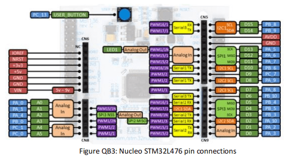
3. Figure QB3 shows the pin connection diagram for the Nucleo board. Which pin(s) could be used to interface to the BMP180 12Coutput. Explain why we could not use D1 or D0.
4. The temperature values from the BMP180 need to cover the range -20 QC to +70 ec. Describe (more than just the name) a suitable 8 bit numbering system that would cover this range, and write down the binary values that would be used to represent -20 and +70. Show a calculation that would enable the binary value for -20 to be converted to decimal.
 All Study Co-Pilots are evaluated by Gotit Pro as an expert in their subject area.